Rust powered atmega328 project meets F1 track Spa-Francorchamps
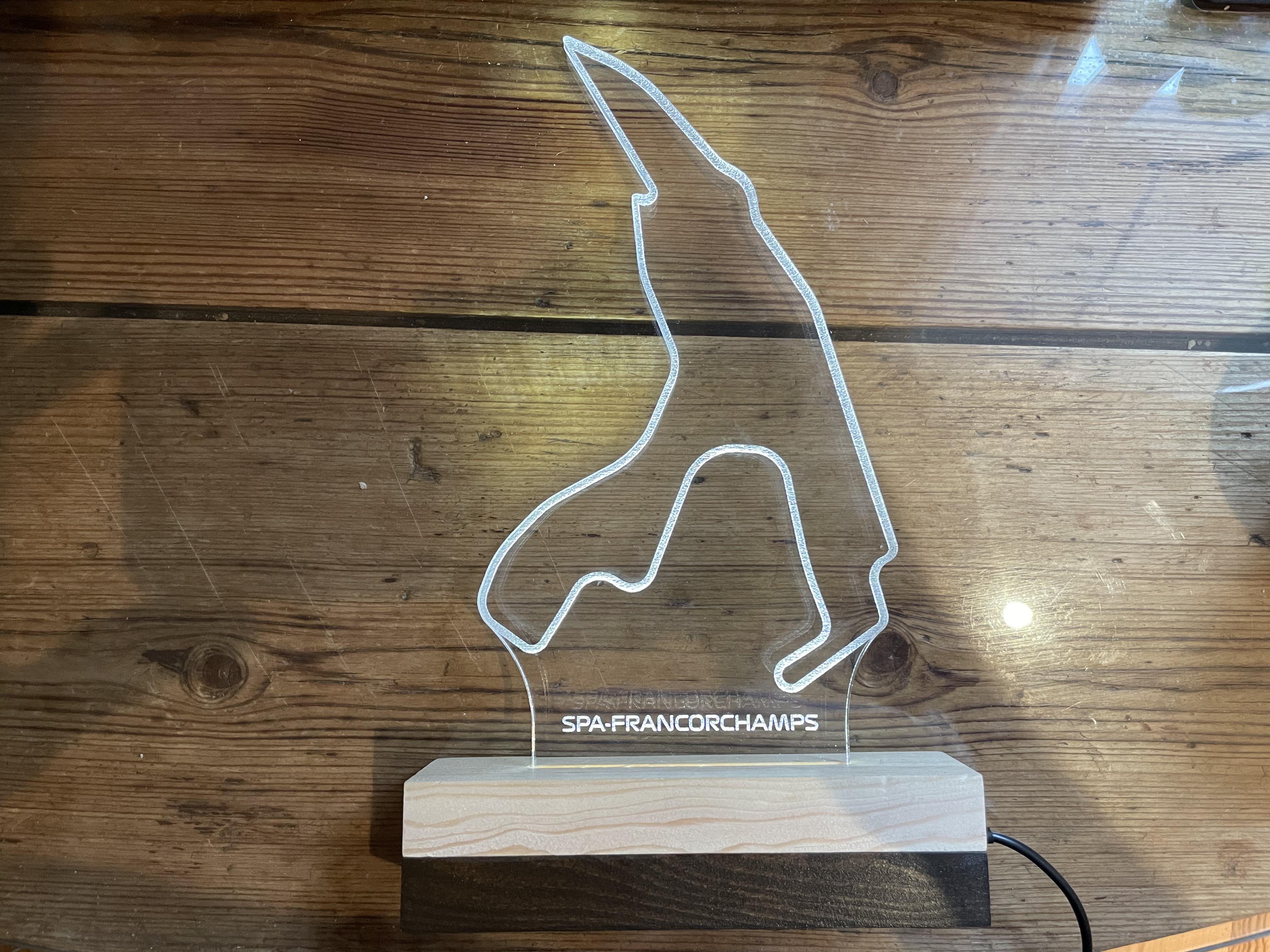
Happy new years everyone! This Christmas I got an awesome light up laser cutout of my favorite Formula 1 track Spa-Francorchamps (home of the F1 Belgian Grand Prix) from my awesome girlfriend. I love the gift and thought I could really bring it to life by adding some “smarts” to the LED lights that power it, and since I’ve been working so much in rust, figured it was a great excuse to get into avr-rust.
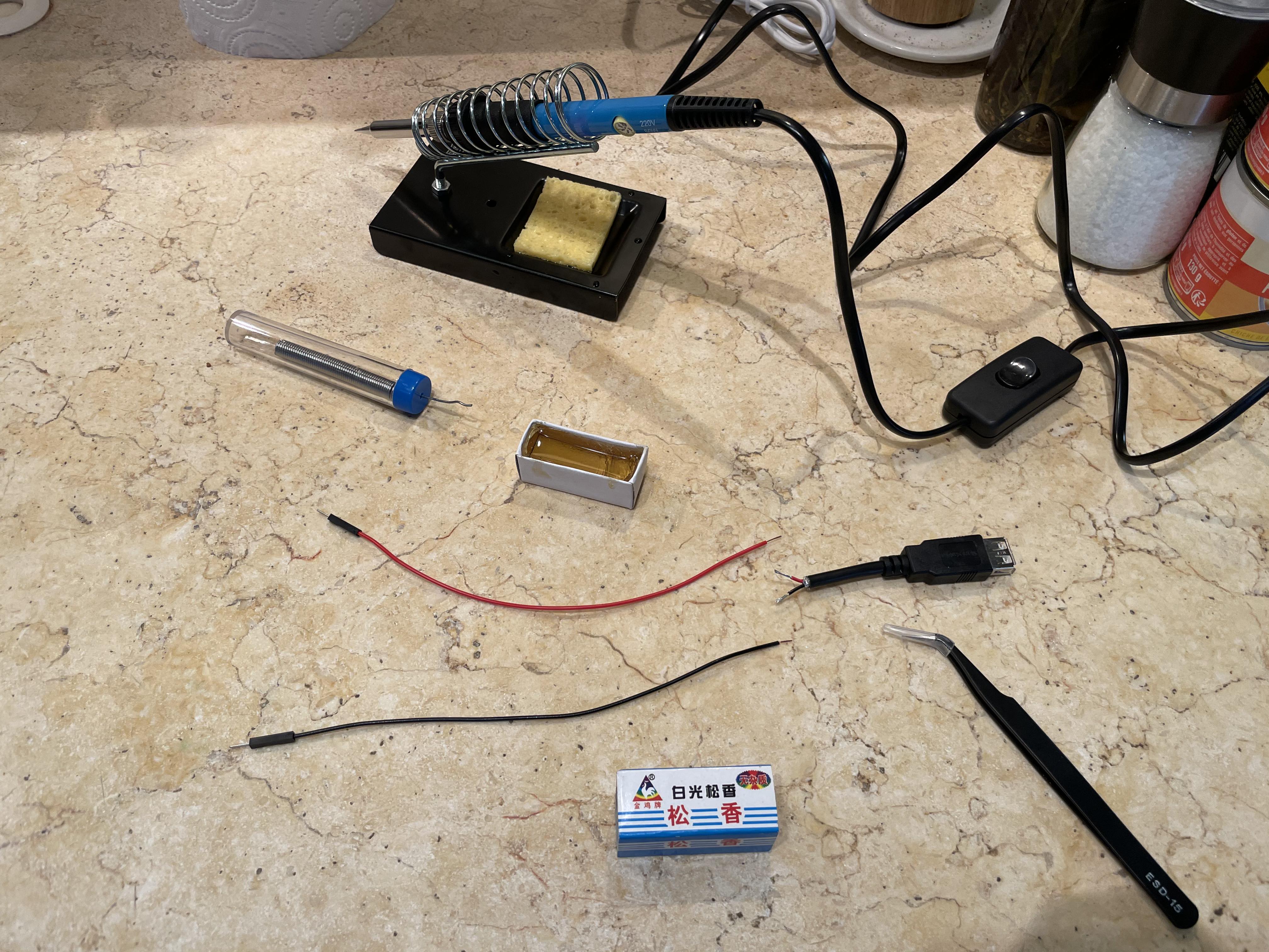
I decided to get a clone of an arduino-uno (basically just an Atmega328p) as well as a relay board (to switch the power supply for the track). The track is powered via a USB 2.0 cable and instead of cutting it I ordered a USB extender and cut that. I didn’t have any of my previous equipment here in Paris so I had to buy a soldering kit with some tools.
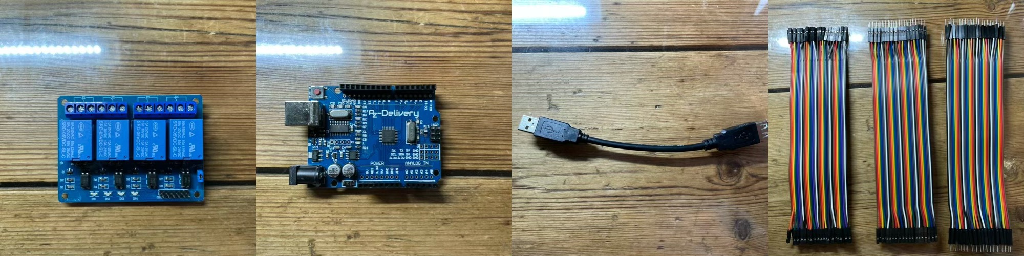
Relay board, off-brand arduino uno, usb extender cable, jumper cables
I had purchased the relay board because I thought the LEDs powering the F1 track might draw too much current to drive it directly from the arduino digital output pin (my plan was to have the digital pin control the relay which would switch the external DC current). But using my USB multimeter, it turns out that the track only draws around 10mA.
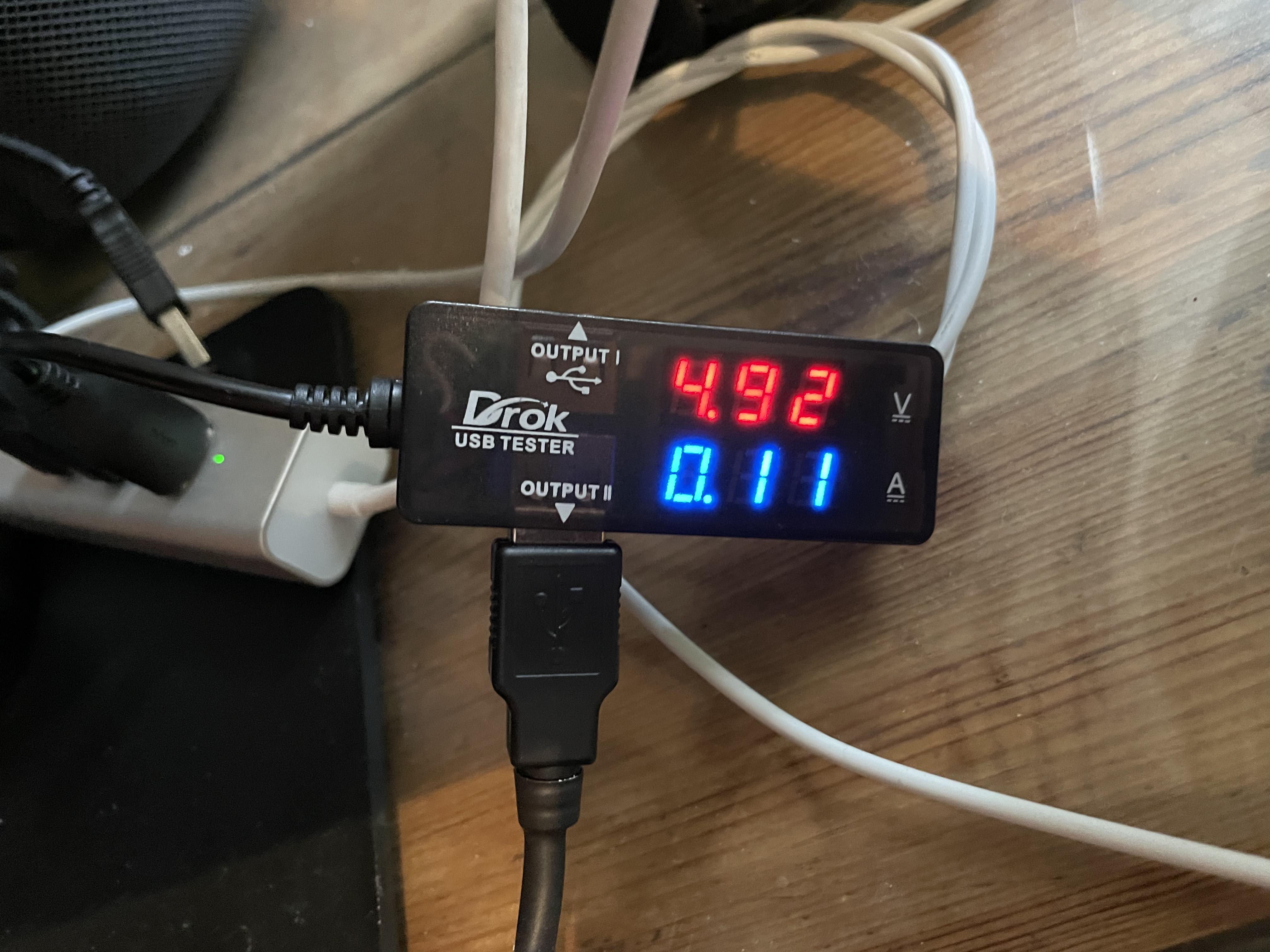
So it looks like we’ll be able to directly power the track through the arduino board, which simplifies the wiring required.
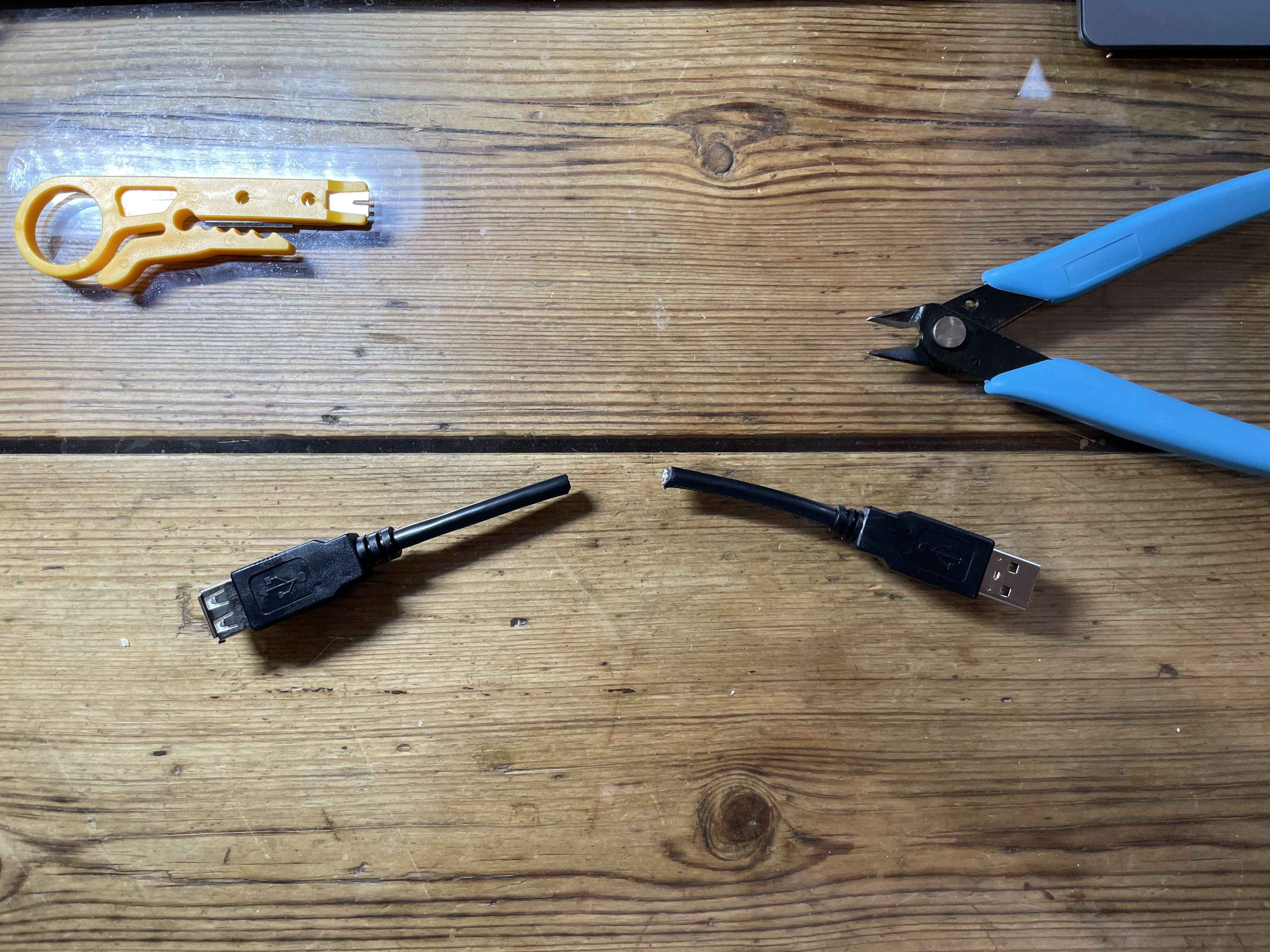
Cutting up the adapter cable
Using a wire cutter I spliced the USB extender in half
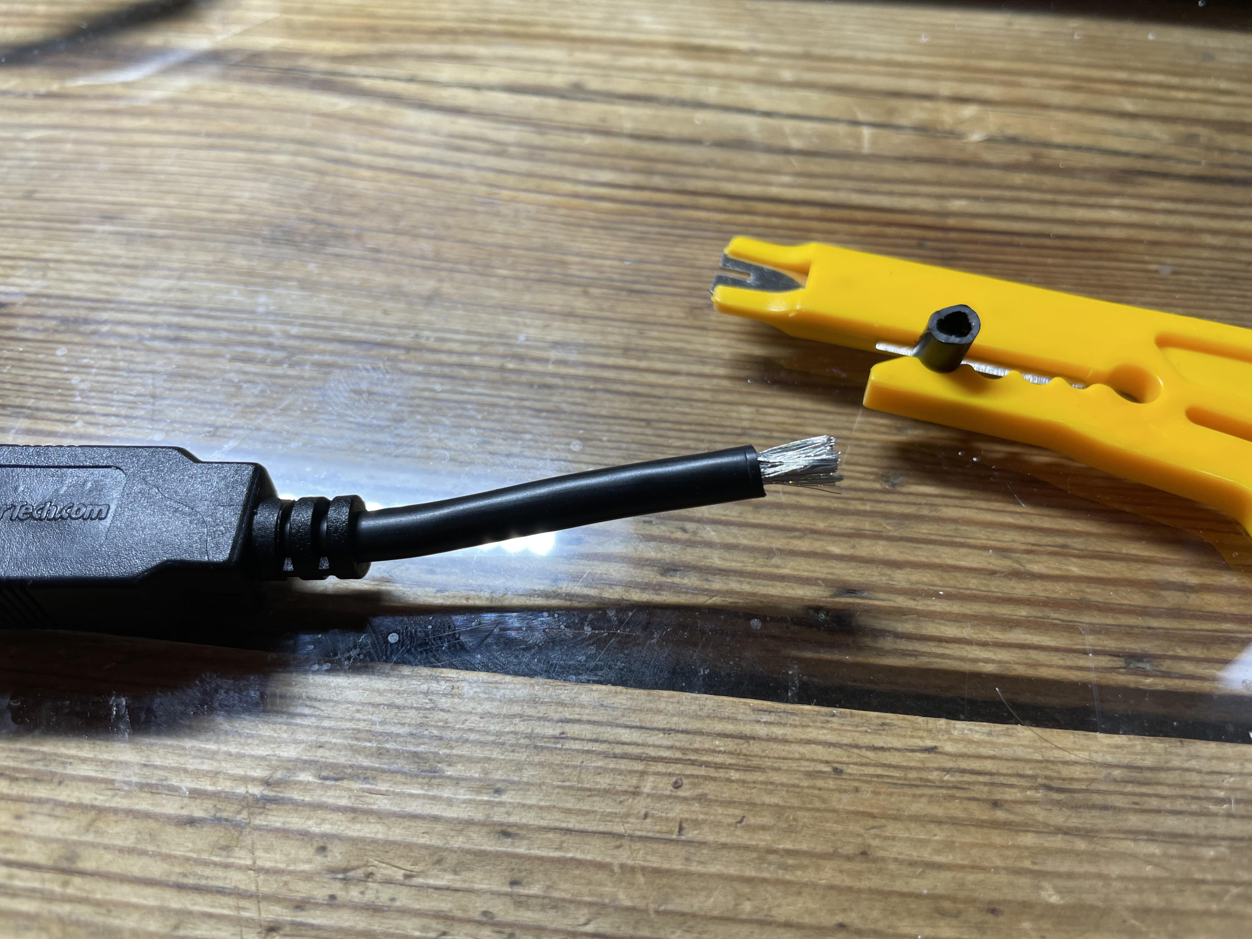
I then used a wire stripper to remove the outer insulation plastic
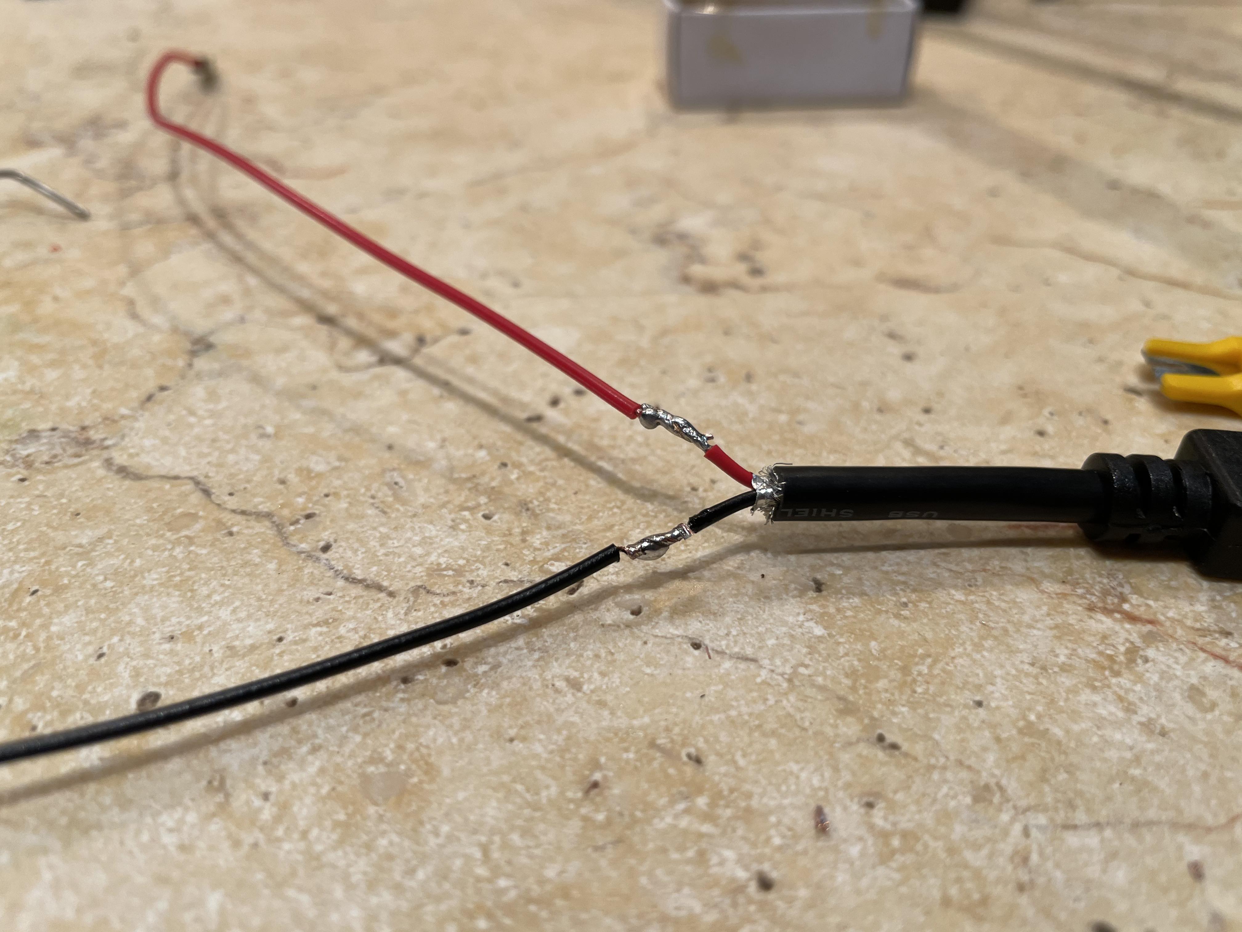
USB 2.0 wires are fairly simple, only have four lines. Two for power (VCC and Ground) and two for data (Data+ and Data-).
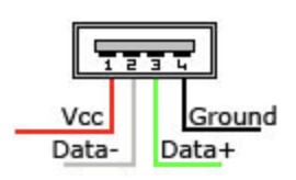
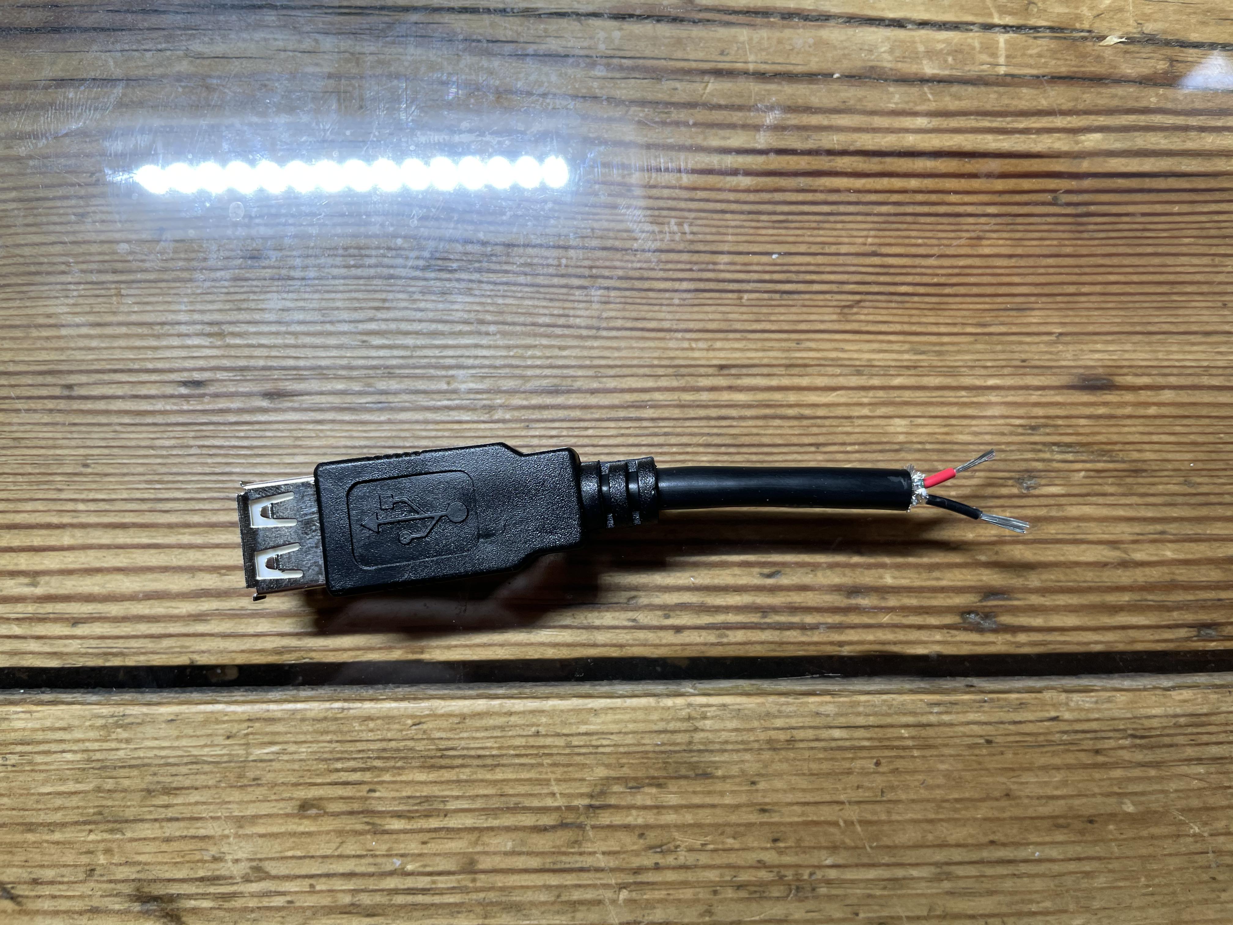
Since the F1 track only uses the power lines for the LEDs, we can safely remove the exposed data lines.
Soldering the adapter cable
Now we need to solder these to arduino jumper cables so we can easily plug them in to the arduino breakout board to power directly.
I simply wrapped the exposed wires around each other and soldered them directly.
And since we don’t want the 5V VCC line to short with the ground one I used electrical tape to insulate the solder joints
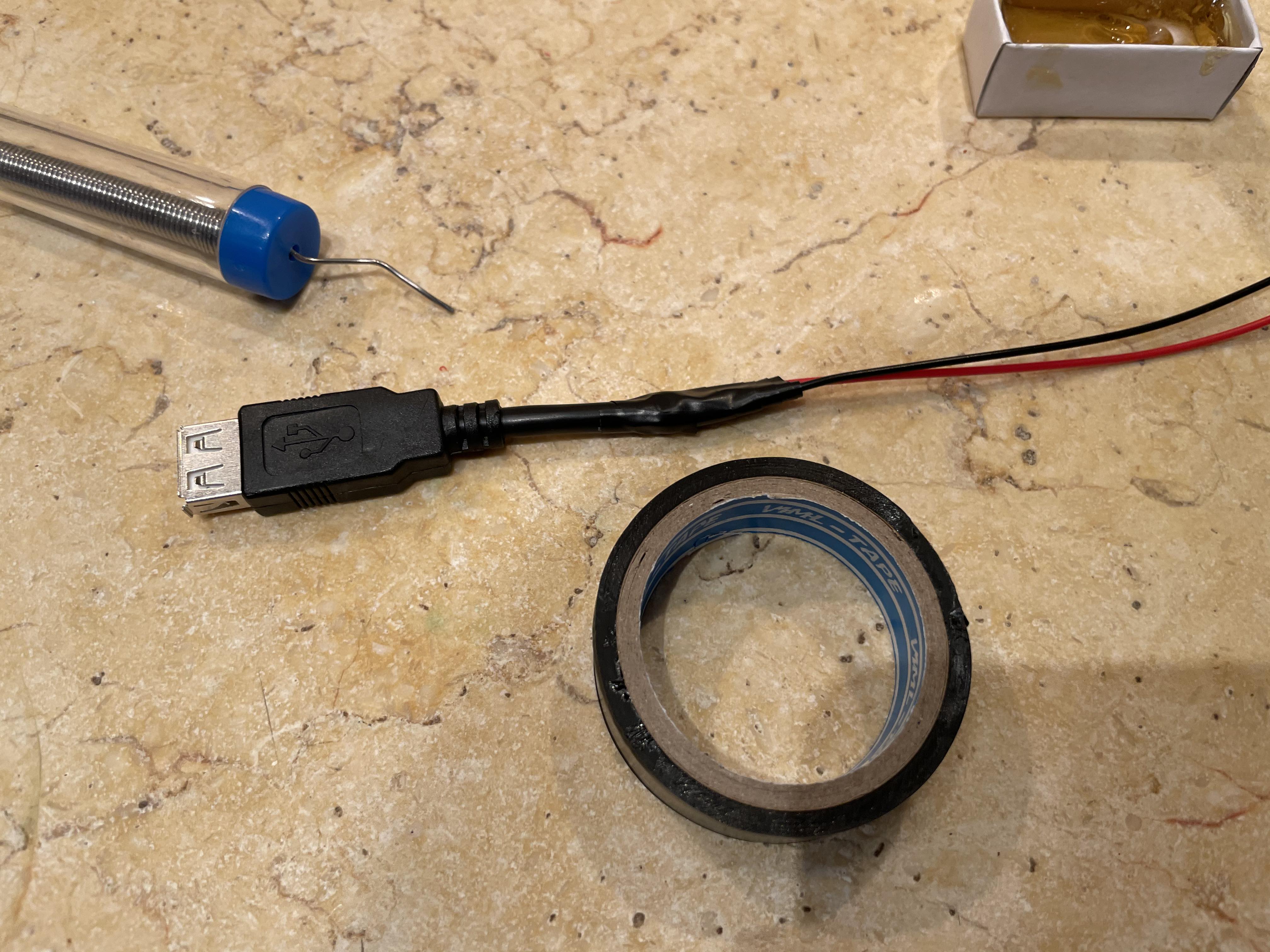
The cable is now ready! Next up is software
Setting up avr-rust
Next I had to set up avr-rust on my local development machine. Using rustup
it’s as simple as
rustup component add rust-src --toolchain nightly
Then using homebrew we need
brew tap osx-cross/avr
brew install avr-binutils avr-gcc avrdude
Rustyspa project
I created a very simple crate that uses PWM with a modulating duty cycle to
fade in and out the lights on the F1 track. It uses avl-hal to interface
with the arduino hardware and avrdude to flash it.
The full source code is all available here but the main source code is simple
#![no_std]
#![no_main]

extern crate panic_halt;
use arduino_uno::hal::pwm;
use arduino_uno::hal::pwm::Timer1Pwm;
use arduino_uno::prelude::*;

const STEP_SLEEP_MS: u16 = 10;
const ON_SLEEP_MS: u16 = 250;
const OFF_SLEEP_MS: u16 = 100;

#[arduino_uno::entry]
fn main() -> ! {
    let peripherals = arduino_uno::Peripherals::take().unwrap();
    let mut pins = arduino_uno::Pins::new(peripherals.PORTB, peripherals.PORTC, peripherals.PORTD);

    // create a PWM timer
    let mut timer = Timer1Pwm::new(peripherals.TC1, pwm::Prescaler::Prescale64);
    // get pin D9 in PWM output mode
    let mut led = pins.d9.into_output(&mut pins.ddr).into_pwm(&mut timer);

    // enable PWM cycle
    led.enable();

    let duty_range = 0..=led.get_max_duty();
    loop {
        for i in duty_range.clone() {
            led.set_duty(i);
            arduino_uno::delay_ms(STEP_SLEEP_MS);
        }
        arduino_uno::delay_ms(ON_SLEEP_MS);

        for i in duty_range.clone().rev() {
            led.set_duty(i);
            arduino_uno::delay_ms(STEP_SLEEP_MS);
        }
        arduino_uno::delay_ms(OFF_SLEEP_MS);
    }
}
Final product
For now this is the final product! A smoothly fading Spa-Francorchamps! Next up I will want to set up schedules for it to turn on and other special effects, maybe synchronize it to music.